device is the
amplifier (MRF 455 ‡ 60 watts max rf power or MRF 454 ‡80 watts rf
power)
power)
The purpose of this amplifier is to lower output energy from output
transistor inside the radio and give strong modulation at higher deadkey
than a power peaked radio with less modulation.
I tell you something I have 2 of these amplifier and I have sold one
and results are very honest (big audio with nice output power)
But I know it’s not 250 watts, however it’s better than a peaked radio with
low modulation)
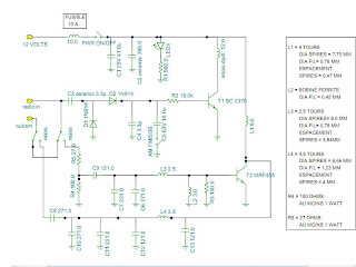
12Volts: connect power source here
Radio in: connect the radio here
Out/ant: connect antenna here
Power on indicator:
Led1 and R1 are used to indicate to user that 12 volt is applied to amplifier
RF detection and switching system:
C3 block any DC path between radio and RF amplifier
D1 and D2: these diodes rectifiers the RF voltage to produce DC voltage in
conjonction with C5, C4
R2 is a current limiter to prevent to smoke T1
T1 activate the relay dpdt 12Volts
RF circuit:
T2: RF power transistor, this is the central unit, this device is the
amplifier (MRF 455 ‡ 60 watts max rf power or MRF 454 ‡80 watts rf
power)
power)
R4 and R5: these resistor network is used to applied the desired
carrier amplitude to the RF power transistor (T2)
C7,C6,L3 are used to filter and make a bandpass network at the input
of T1
L2, R3 used to make class C operation
L1, it’s a RF choke, block RF energy to take path in DC supply
C10, C11, C12,C13 and L4 are used to make and resonnant circuit to
produce an output waveform with no distorsion.
C8 and C9 these capacitors block DC voltage
Tips and tricks about this amplifier:
You have to connect your power supply ground to case of your amplifier
Of course the shield of your coax will be connected via the PL259 to your
Amplifier. Also make a good connection to power supply ground to your
RF circuit ( if you want that your circuit being supply ;) )
If you want to adjust sensitivity of your RF power transistor
spread more or least L3. Mine key with 0.6 watt, it’s preserve
my output transistor on my 2950.
Note: When L3 is tight the sensibility is at the maximum.
And vice-versa
It’s possible to add a two stage variable power, check on the schematic
(Low and High)
Fuse should be set to 8 amp.
Don’t put higher fuse because it will not protect your amplifer
Great modulation appear at 35 watts and swing up to 55-60 watts
On my side it’s really loud and clear.
MRF455 is a 60 device and needs a lower deadkey than the MRF454 (80
watts)
MRF455 is a 60 device and needs a lower deadkey than the MRF454 (80
watts)


0 comments:
Post a Comment